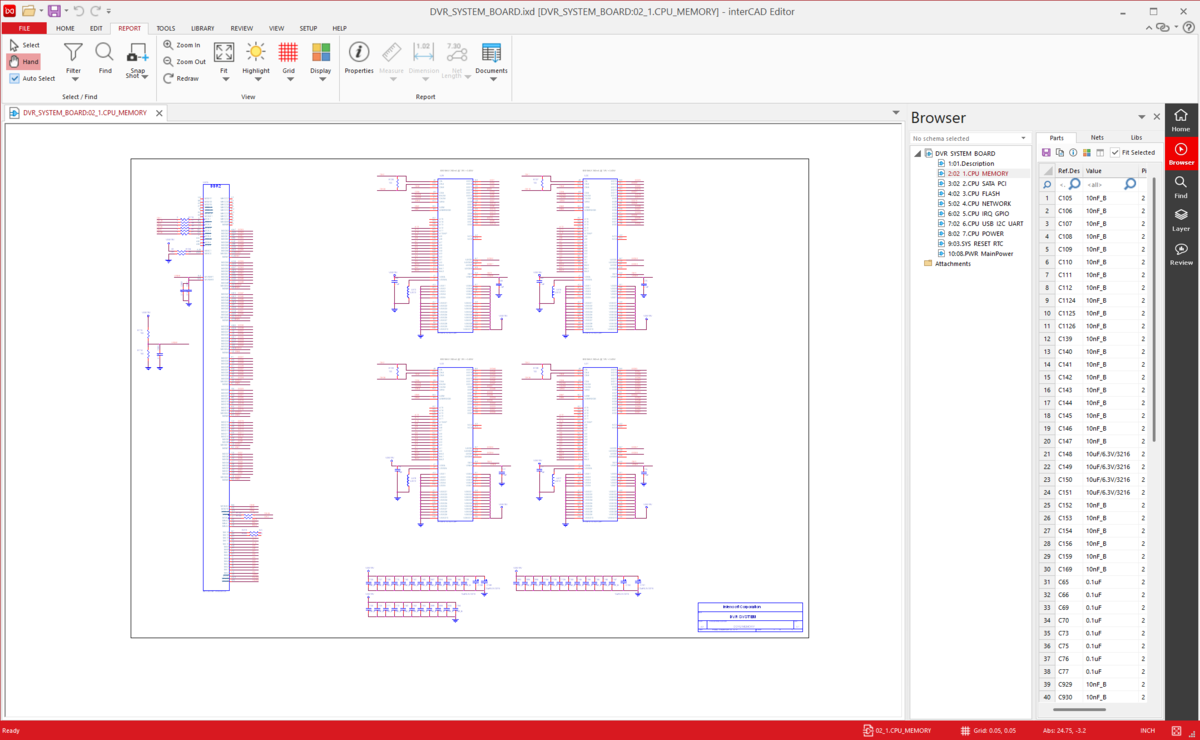
Schematic Viewer

Schematic Viewer is an electronic circuit viewer that allows you to visually view symbols and connection (Net) information of electronic circuits. Provides intuitive and efficient visualization to clearly communicate design intent for circuit design review, collaboration, documentation, and more.

View other supported
interCAD schematic viewer
import

Import file format

Schematic Viewer supports various schematic data. It is compatible with universal formats, so it can be used in various design environments.

  • EDIF Schematic
  • Altium Designer Schematic
  • OrCAD Capture
  • PADS Designer
  • Xpedition Designer
  • Zuken Schematic
* Allegro, Board Station, Xpedition, PADS Pro, Zuken The file requires Tool Installation and License.

Review

It provides a Review function that allows you to insert annotations directly into schematic drawings, preventing communication errors during exchange of opinions and design reviews between workers.

  • Click-based annotation insertion
  • Real-time feedback and review history management
  • Improving information delivery in collaborative environments
design review
app cross probing

Cross Probing - APP LINK

Schematic Viewer automatically navigates, moves, and zooms in on objects (Components, Pins, Nets, etc.) within a circuit when selected through integration with external schematic tools.

Hotkey

You can use the same mouse operation and shortcut key environment as the existing Schematic tool, and it also supports user-defined settings so you can adapt quickly.

hotkey
snap shot

Snapshot

You can create a snapshot by specifying the required design area, and the image will be automatically copied to the clipboard.
The copied image can be used immediately in various environments.

Open Library

View a library of components included in your design within the Viewer, and get precise measurement capabilities for design elements such as symbol-to-symbol distances and pin-to-pin spacing.

open library
report

Report

You can extract and document analysis results based on design data.
The output information can be used for various purposes such as circuit analysis.

  • Part list output

Additional features

measure icon

Measurement

It can accurately measure distance between circuits, component spacing, size, etc.

highlight icon

Hightlight

Click on the desired component, net, trace, etc., and only that item will be visually highlighted.
Even in complex designs, you can quickly track only the information you need.

×

interCAD, Start Free Trial now!

Familiar environment,  powerful performance, and one-click start.

KakaoTalk inquiry Go to top