Compare files

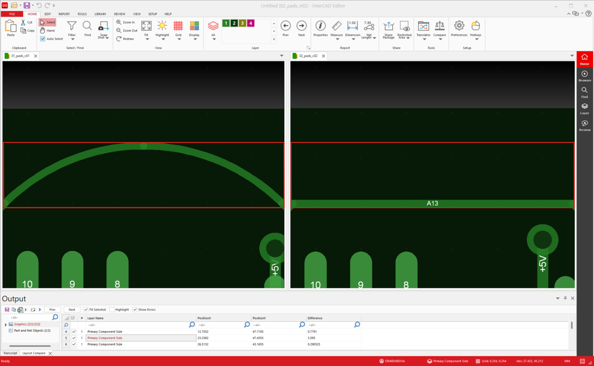
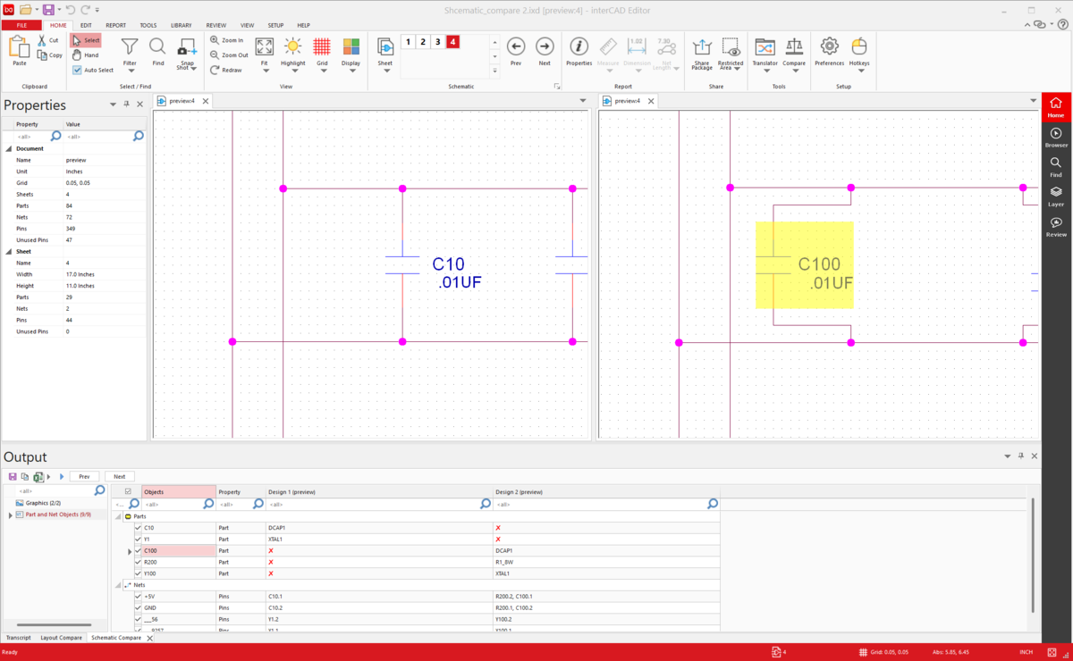
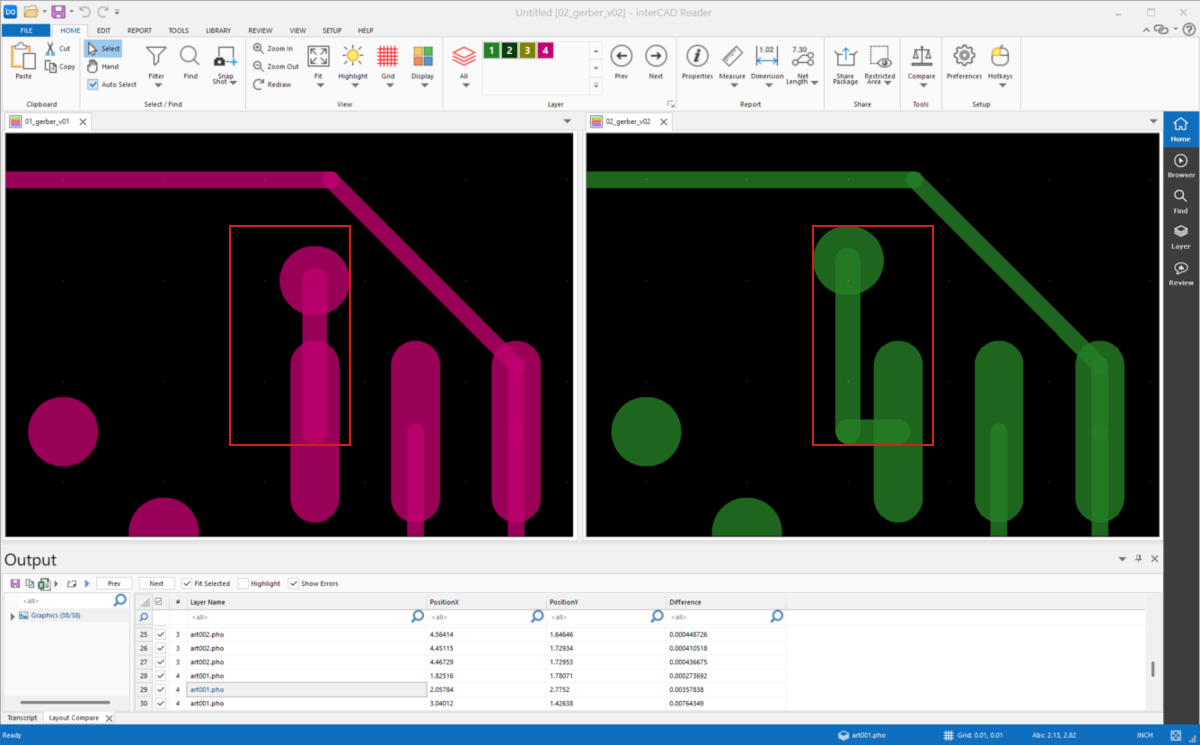
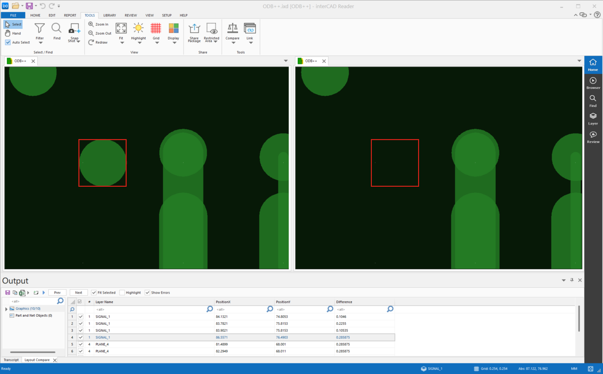
interCAD Compare is a dedicated solution that helps you quickly and accurately compare and identify differences between two ECAD design designs. It supports various ECAD data formats such as Schematic, Layout, Gerber, ODB++, etc., and enables detailed and intuitive design change verification based on graphic and attribute information.

interCAD compare

Support comparison format

schematic compare

Schematic Compare

pcb compare

PCB Compare

gerber compare

Gerber Compare

odb compare

ODB++ Compare

Main features

compare file

Review changes

interCAD Compare allows you to compare the entire design or just specific areas.

Specific Area: Users can select only the area they want to focus on and analyze the differences in a specific area.
All Layer: Compare all layers of the entire design at once to comprehensively review changes.

This provides flexible comparative analysis tailored to your usage needs.

Graphic-based comparison

interCAD Compare provides an intuitive and clear image-based graphical representation of the differences between two design files.
It allows you to see the shape changes and design modifications of two designs at a glance, and supports more accurate judgment during the design verification process.

graphic compare
property compare

Compare property information

interCAD Compare compares the attribute information of all design components, including parts (Partlist), VIA, and NET (Netlist), to clearly identify differences.
It provides a list of attribute changes between components, enabling efficient design change verification.

Automatic Highlight & View matching

Automatically highlights areas where differences are detected, making them visible.
interCAD Compare allows you to clearly see the areas and information that have changed, increasing the efficiency and accuracy of your verification work.

highlight
output

Output

You can output the detected differences in Excel format. This can be effectively used for tasks such as creating work instructions or managing design change history.

FAQ

How accurately is it verified?

The Compare function in interCAD Editor can achieve 100 percent accurate verification depending on the value of the ignore difference area option.

How do you do the comparison?

The Compare feature in interCAD Editor compares drawings in two ways

1. Image-based graphical comparison

2. Part and Net Objects comparison based on drawing properties

This allows you to effectively identify differences between drawings.

What drawings can I compare?

interCAD Editor supports comparison between schematics (Schematic), PCB (PCB Layout), and CAM (Gerber, ODB++) drawings.

However, comparison between schematics and PCB drawings is not supported, and only comparison between schematics, PCBs, and PCBs and CAM drawings is possible.

An error window pops up when comparing.

This error occurs when the units of the drawings being compared are different.

The solution is to set the units of each drawing to be the same in Home → Preference → Design Options in the top menu of interCAD Editor.

If the units are aligned, you can proceed with the comparison without errors.

It's the same drawing, but when compared, different areas are compared.

interCAD Editor compares graphics and objects based on the Origin (reference point) of the drawing.

Therefore, if the Origin of each drawing is different, there may be differences in the comparison results.

To change the Origin, select Edit → Move → Set Origin from the top menu of interCAD Editor to reset the Origin of the drawing.

Learn more
×

interCAD, Start Free Trial now!

Familiar environment,  powerful performance, and one-click start.

×
KakaoTalk inquiry Go to top