PCB Viewer

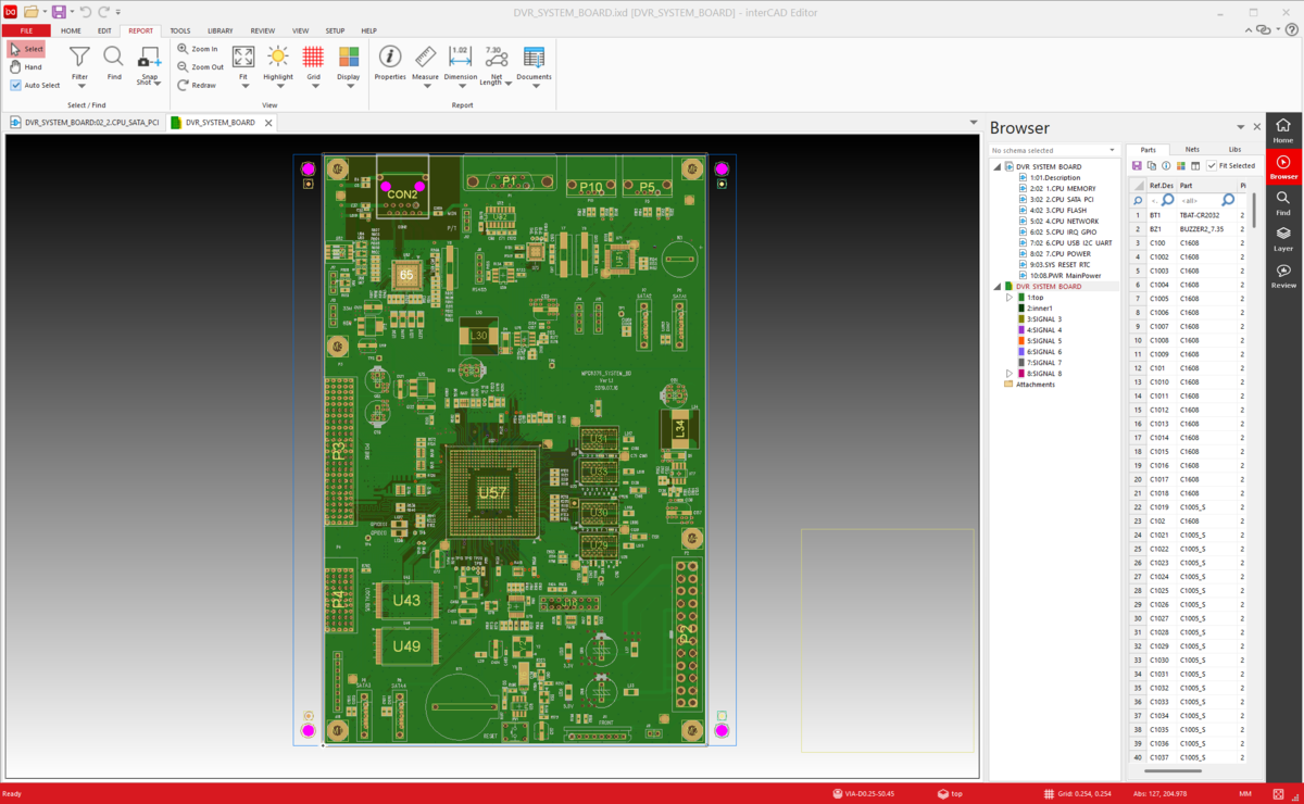
PCB Viewer is a viewer that allows you to visually view and review design data for printed circuit boards (PCBs).
It allows you to intuitively check various design elements such as component placement, routing paths, and layer information, and provides an efficient visual environment for design review, collaboration, and documentation.

View other supported
interCAD pcb viewer
import

Import file format

PCB Viewer supports layout data generated from the following major ECAD tools:
Integrates various formats to provide a compatible review environment.

  • Allegro PCB Design
  • Altium Designer Layout
  • Board Station Layout
  • PADS Layout
  • PADS Professional Layout
  • Xpedition Layout
  • Zuken Layout
* Allegro, Board Station, Xpedition, PADS Pro, and Zuken files require Tool installation and License.

Review

Provides a Review function that allows direct insertion of annotations into PCB drawings, visually enhancing feedback and collaboration between designers and reviewers. This can reduce design errors and communication risks.

  • Click-based annotation insertion
  • Real-time feedback and review history management
  • Improving information delivery in collaborative environments

design review
app cross probing

Cross Probing - APP LINK

PCB Viewer is integrated with ECAD tools, so when you select a specific object (component, pin, net, etc.), it automatically pans/zooms to display the same object. This ensures both review speed and accuracy.

Hotkey

PCB Viewer is ready to use immediately, without learning, as it uses or customizes the mouse gestures and shortcuts you are used to using in ECAD tools.

hotkey
snapshot

Snapshot

You can create a snapshot by specifying the required design area, and the image will be automatically copied to the clipboard. The copied image can be used immediately in various environments.

Open Library

You can browse the library of components included in the design, and check information such as gaps between components and pad sizes directly through precision measurement tools within the Viewer.

open library
report

Report

You can extract and document analysis results based on design data. The output information can be used for various purposes such as design verification, BOM creation, and circuit analysis.

  • Part list output
  • Netlist output

Additional features

measure

Measurement

It can accurately measure distance between circuits, component spacing, size, etc.

highlight

Hightlight

Click on the desired component, net, trace, etc., and only that item will be visually highlighted. Even in complex designs, you can quickly track only the information you need.

×

interCAD, Start Free Trial now!

Familiar environment,  powerful performance, and one-click start.

KakaoTalk inquiry Go to top